February 29, 2012

S2 vs S3


Black: Measured S2
Red: Simulated S2
Green: Simulated S3

My design for S3 is now very nearly ready for construction. The bandwidth is wider, with a smother response, equal bottom end extension, greater top end extension and higher sensitivity. 

February 28, 2012

Akabak vs Hornresp vs Real measurements

Here is a chart that shows the results from Hornresp vs Akabak when compared to the measurements of the actual real thing:


Black is the measured response of the 4" closed back midrange on S1. Red is Hornresp, green is Akabak.

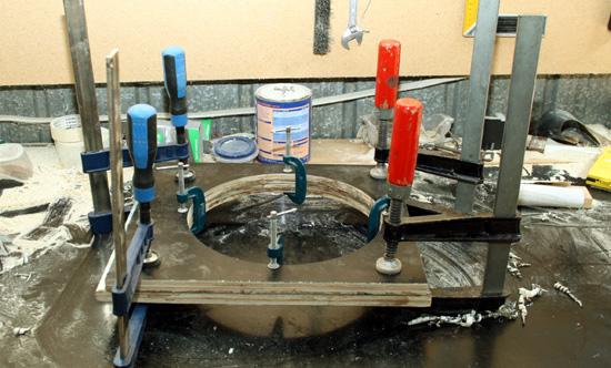
S1 is a 60 x 60 point source horn:


Note: Pyle drivers shown are not what is being investigated here.

Here are the Hornresp parameters:


Included at the end of this post is the script for Akabak. I exported the script from Hornresp, so it was automatically generated.

You will notice an offet of the ports larger than built - 9.2cm was entered as it matches the first dip. The ports were located 8.6cm from the throat - a 7% difference. This could be related to the compression driver exit tube coming into play, or it could be related also to atmospheric conditions and the speed of sound which is  used to determine the port offset.

In this example it's interesting to see that Hornresp is actually more accurate where it matters most. In particular I'm interested in the top and bottom end roll off behaviour as it assists in choosing the parameters. Hornresp is closer with both. It estimates the first dip well enough to guide design decisions and then becomes very inaccurate at higher frequencies where the crossover takes over. In the bottom end, both fail to predict the peak and dip.


Akabak script generated by Hornresp:


|DATA EXPORTED FROM HORNRESP - RESONANCES NOT MASKED

|COMMENT: Celestion 4" single on S1

|========================================================================================================

|REQUIRED AKABAK SETTINGS:

|File > Preferences > Physical system constants:

|Sound velocity c = 344m/s
|Medium density rho = 1.205kg/m3

|Sum > Acoustic power:

|Frequency range = 10Hz to 20kHz
|Points = 533
|Input voltage = 2.83V rms
|Integration = 2Pi-sr
|Integration steps = 1 degree ... 1 degree
|Integration method = Cross

|========================================================================================================

Def_Const |Hornresp Input Parameter Values
{
|Length, area and volume values converted to metres, square metres and cubic metres:

S1  =     4.90e-4;  |Horn segment 1 throat area (sq cm)
S2  =   100.00e-4;  |Horn segment 1 mouth area and horn segment 2 throat area (sq cm)
S3  =  2500.00e-4;  |Horn segment 2 mouth area (sq cm)

L12 =     9.20e-2;  |Horn segment 1 axial length (cm)
L23 =    33.00e-2;  |Horn segment 2 axial length (cm)

Ap  =     2.50e-4;  |Chamber port cross-sectional area (sq cm)
Lpt =     1.80e-2;  |Chamber port tube length (cm)

Vtc =    34.00e-6;  |Throat chamber volume (cc)
Atc =    55.00e-4;  |Throat chamber cross-sectional area (sq cm)

|Parameter Conversions:

Sd  = 60.00e-4;  |Diaphragm area (sq cm)

Ltc = Vtc / Atc;
}
|========================================================================================================

|Network node numbers for this offset driver horn system:

|       0-Voltage-1
|                 |
|Radiator(1)-5-Driver-6-Chamber-7-Port-
|                                      |
|                            8-Segment-9-Segment-10-Radiator(2)

|========================================================================================================

Def_Driver 'Driver'

  Sd=60.00cm2
  Bl=6.49Tm
  Cms=3.01E-05m/N
  Rms=0.98Ns/m
  fs=444.4946Hz  |Mmd = 4.00g not recognised by AkAbak, fs calculated and used instead
  Le=0.60mH
  Re=5.69ohm
  ExpoLe=1

System 'System'

  Driver Def='Driver''Driver'
    Node=1=0=5=6

  Radiator 'Diaphragm'
    Node=5
    SD={Sd}
    Label=1

  Duct 'Throat chamber'
    Node=6=7
    SD={Atc}
    Len={Ltc}
    Visc=0

  Duct 'Port'
    Node=7=9
    SD={Ap}
    Len={Lpt}
    Visc=0

  Waveguide 'Horn segment 1'
    Node=8=9
    STh={S1}
    SMo={S2}
    Len={L12}
    Conical

  Waveguide 'Horn segment 2'
    Node=9=10
    STh={S2}
    SMo={S3}
    Len={L23}
    Conical

  Radiator 'Horn mouth'
    Node=10
    SD={S3}
    Label=2

February 27, 2012

S3 sneak peek

S3 will probably look like this:

 Easier to mount the drivers onto the 60 degree vertical walls. 

The outer flare at the mouth will have a smoother transition than previous versions.


February 23, 2012

Saturday is badass bass day!

This Saturday I'm hosting a badass bass day. Included will be:

  • F20 - a 20 Hz front loaded horn with dual Acoustic Elegance PB10 10" woofers, 95 dB sensitivity down to 20 Hz
  • T20 - a 20 Hz tapped horn with dual Rythmik 12" servo subs, 93 dB sensitivity, 120 dB max SPL
  • Maelstrom X2 18" in a 120L aperiodic box
  • 2 x AE TD18H 18" pro woofers in 100L sealed boxes
  • 2 x Eminence Magnum 18LF 18" pro woofers in 60L sealed boxes
I'm particularly interested to compare TD18 to the Eminence woofers. Could be a future upgrade. We might also compare T20 and F20 although the comparison is obscured by different placements. The Maelstrom will sit on top of F20 in the front middle wall position. We might compare them as well.

T20


F20


TD18H boxes (they have progressed further than shown)


Eminence boxes


The Maelstrom will go in a prototype box I have lying around.

How does the sensitivity of tapped horns compare?

Here is a simulation to illustrate. This is based on a Hornresp simulation that has been exported into REW for comparison:


In light blue you can see dual Rythmik 12" servo subs in a sealed box with 1w input. Around 88 dB nominal sensitivity which drops to 80 dB at 20 Hz. The black line shows T20, a 20 Hz tapped horn with around 500L volume. The nominal sensitivity at 100 Hz can't be compared, however it is 89 dB at 20 Hz. 

The dark blue line shows the excursion limited maximum output. Around 370w shared between the two drivers has the driver reach excursion limits. 106 dB max SPL at 20 Hz. The tapped horn increases sensitivity and controls excursion more so that the full 740w can be used and excursion limits are reached around that point. The output is 118 dB, which is a 12 dB increase in output. 

So the result is that two 12" drivers with 370 watts each can achieve the same output as eight with twice as much power. Since drivers and amps are much more expensive than a few sheets of cheap ply, this works out as a cost effective choice.

February 12, 2012

February 11, 2012

T20 Rythmik dual opposed tapped horns - construction

Construction of T20 has now begun. 


I've paid extra attention to the area where the drivers are mounted. There are two main issues with a sub. One is dealing with vibration from the drivers, the other is dealing with acoustic pressure. The area where drivers are mounted are given extra attention because that is where mechanical vibration is transmitted. Dual opposed design reduces this a great deal. You can't see it here, but the driver baffles sit into a groove in the end to firmly hold them in place. At this point they are attached with polyurethane glue which is very strong. Dual baffles and as much bracing as possible. 


Drivers will be installed via external hatches.


Progress has been slower than with F20 and the bass bins because a little more care has been taken over certain details, some of them now shown. Driver cut outs were cut all the way through with the router.

This is intended for a permanent installation under the floor. If I'm happy with the result then it will stay for quite some time.

TD18 bass bins - glass reinforced filler


Painting over butt joins is always a problem. Here I've cut grooves with the router, filled with bog and now I've used automotive fibreglass reinforced bog, buttered over the joins like icing a cake.


February 8, 2012

Progress on TD18 bass bins and F20

Grooves have been filled with bog, but still need more:


Rear:


Rythmik DS12 driver on top of F20 for scale:


Rythmik T20 baffles

Double layer baffle (2 x 17mm formply). Holes cut with a router jig, then sanded rough and glued together with construction adhesive.


After removing the "ooze." 


February 7, 2012

TD18 bass bins

Grooves over butt joins to be filled:


Polyurethane glue was  used to add the baffle as it expands to fill voids. 


Sanding in progress:


F20 build pics

F20 assembled:


February 4, 2012

More progress - AE TD18 bass bins and F20 bass horn

Two bass bins now assembled sans outer baffle. 


Internal bracing:


I wasn't quite careful enough drilling into the ply, so it split apart. I used polyurethane glue to repair it. In the past I've used PVA but it's difficult to get the glue in. With PU glue it expands to fill the void, so that it pushes the glue both into the void and out. The glue seen on the outside is there only due to the expansion. This glue is four times stronger than PVA.


F20 part-assembled:


Driver cut-outs were done with a router jig: