December 29, 2010

Building a 6" oblate spheroid waveguide

Can't be that hard, can it?

It sounds simple enough. Draw up the profile, cut up some MDF donuts, glue together, turn it up on the lathe. Voila! Waveguide bliss. I was thinking about 3 - 4 hours and that I'd get to do other things that day. Well, it took about 3 days! 

It has an acrylic mounting plate because it's a bolt-on driver.


Here are the parts:


The tricky part is getting them all concentric. I spent about half an hour just talking with my construction advisor (aka Dad). That had me worried. I knew if it took half an hour just to talk about how to do it, my 4 hour plan wasn't looking good. 

Gluing - the easy part:


I had to leave a 1/4" hole through all the pieces, then line up with a metal rod. 


That had to be aligned to a metal flange that attaches to the lathe, which meant machining up another rod with an adaptor, which you can see above sticking out the top. 

Once glued, I then cut out the centre circles.


All this to avoid having to chisel out the whole thing very slowly on the wood lathe:


It's a fairly slow process where a chisel is held on to the metal guide. You have to keep stopping to test against the template (paper cut out). I have used this method in the past to create flared vent ends. 

Action shot: 


I realised that it would be quicker and easier in the metal lathe. The wood lathe actually isn't a lathe but a multi purpose shopsmith that works as a drill press, table saw and sander. The metal lathe is a proper lathe and more accurate but limited in the size it will turn.


Finished waveguide:

It was very time consuming to build and turn the first, but once it was done, the second was quick to turn up. I spent 3 days on the pair - probably about 16 hours. I could probably build them again in half a day.

The final result:

More about my prototype speaker >

Oblate spheroid waveguides

An oblate spheroid is the Rolex of waveguides and horns. It is the ideal choice for high frequency compression drivers where sound quality and constant directivity are the main goals. If those aren't your goals, they should be! When using loaded compression drivers, you have a few strong advantages:
  • ability to achieve controlled directivity
  • ability to choose coverage angle to match the polar response of the midrange driver
  • very high efficiency and output
All horns in this application make at least one big compromise. The first is to use diffraction to achieve controlled directivity. This results in poor sound quality due to a much larger amount of higher order modes (HOMs), which according to Geddes is the main cause of sound quality issues with horns. The second is directivity. The popular tractrix profile is considered one of the better sounding HF horns, but the response narrows with increasing frequency.

This begs the question "why still use HF horns?" There are some who are tolerant of horn coloration and who are less concerned with directivity. The latter is one of the most overlooked issues in audio.


What about conical?

Conical waveguides are similar, but differ most at the throat which is the most critical area. A compression driver like the B&C DE250 has a conical exit tube with a 6 degree taper. When loaded into a conical waveguide, a sharp transition of 6 to 45 degrees is formed. This causes diffraction at the throat and more HOMs. The oblate spheroid waveguide has a gradual transition after which the two are the same. It takes a little more effort to add the transition and some maths is involved, but the oblate spheroid is clearly better.

How to derive the contour

Spreadsheets have been made and Hornresp can also export a text file which contains the co-ordinates of the profile. There are four variables involved:
  • throat area (match to the compression driver exit tube, typically 1")
  • mouth area (match to the mid driver)
  • coverage angle
  • compression driver exit tube angle
 These together determine the contour and axial length, along with the bandwidth. The exit tube of the compression driver determines the high frequency limit - usually just under 20k for a 1" exit. Larger compression drivers have less high frequency extension.

Matching mid drivers

A smaller mouth has less low frequency extension. Normally the waveguide mouth and mid driver should match in size. Some examples

15" mid + 15" (diameter) waveguide - 900 Hz crossover
12" mid + 12" (diameter) waveguide - 1200 Hz crossover
10" mid + 10" (diameter) waveguide - 1500 Hz crossover
8" mid + 8" (diameter) waveguide - 1800 Hz crossover
6" mid + 6" (diameter) waveguide - 2000 Hz crossover

This should work with a 90 degree oblate spheroid waveguide, where both will have matching directivity at the crossover, then the response will widen until it is omni directional at bass frequencies. The high frequency response will have near constant directivity in the waveguide bandwidth. As a result, we want to use the waveguide for as much of the range as we can. Size matters.

How much effort?

To design and build speakers like this isn't trivial. For most there are some easier and preferable options. For a fully sorted state of the art version, I suggest Geddes kits where the Abbey is probably the sweet spot.

Gedlee kits >

A cheaper and less refined version is the Econowave. It uses stock waveguides which are cheap and easy to get hold of. There are many drivers that have already been used where the crossover design has already been done.

Introducing the Econowave >

Also similar are Pi speaker kits.

If you are like me and insist on designing and building your own, then expect a challenge! Building a decent waveguide is a lot more difficult than simply building a box. Designing the crossover is time consuming and requires many measurements. In my case, I enjoy the learning process, the challenge involved and my ultimate goal is to create a unique custom made speaker that combines style and performance like a highly tuned sports car.


Read about my 6" prototype >

6" waveguide 3 way prototype


I was curious to see how a compression driver would work with a 6.5" hifi mid. This one is a modified Vifa C17 which is a cheap but decent midbass. It's box sits sideways for closer driver spacing and the compression driver (B&C DE250) is mounted to a matching 90 degree oblate spheroid waveguide. I configured a simple active crossover at 2k, used a single broad PEQ cut filter at 4k and fired them up for a listen. The result is an obvious improvement over the Vifa D19 dome tweeter, even though the crossover has had less attention. Imaging is better and the sound is cleaner.

December 27, 2010

Summer 2010/2011 in the works

Right now I'm building some oblate spheroid waveguides. Just a pair of small 6" guides to mate with a 6" mid. My first go at integrating my new compression drivers. So far (as always) it's taking much longer than expected!

Also planning:

  • large rectangular waveguides - 15" 40 x 90 degree and perhaps an 18" like the Unity
  • some big bass traps (ones that can live permanently in the room)
  • quadratic diffusors and some absorbers
  • under floor bass horns
  • AV rack

This is the mounting plate. The CD needs to be bolted on to a flange. As the WG won't have one, I use an acrylic sheet. 


These are the parts that make up the waveguide. They still need to be aligned, glued and turned up. I had a mishap with the acrylic when drilling. :( This is just a prototype, I keep telling myself. I may get the final one CNC cut.

December 26, 2010

Amplifier classes

Class A operate with their amplifying devices operating over the entire input cycle. That means they stay on the whole time.

Class B operate only half the time. Operate them in push pull and one devices does the + side while the other does the - ve of the waveform.

Class B is much more efficient. A 20w class A will have big heatsinks like a 200w class AB.

Class AB is considered a good compromise, where many start at class A then switch beyond a certain threshold. You get crossover distortion added as a result. Class A is considered more accurate.

Class D is more efficient again because the devices switch fully on or off, rather than operating in linear mode. The signal is converted to a series of pulses. It has been argued that the devices can't switch fast enough to be suitable for HF use.

Class H is essentially a Class AB amplifier with a power supply that is more efficient. Behringer Europower and some other pro amps use this class.

December 22, 2010

Bass Trap measurements

Here is a collection of before and after measurements of bass traps. I started building and measuring my own prototypes with scraps because I wasn't satisfied with what I could find. I wanted to find out if it was worthwhile before giving up space in my fairly small room.

Firstly, this example comes from Ethan Winer at Real Traps. In this example, a small room was treated extensively in a non-obtrusive style.You can see it in his Hearing is believing video.


Now here is my own result with some thrown together temporary bass traps.

The improvement is much more than you would expect from this chart. It was a big improvement in tightness and bass control. I have heard many high end systems and the bass I'm getting here is equal to the best I've heard.

How to read these charts

The most important charts shown are the waterfalls. They are simply a frequency response that is measured over time. At the top of the chart you see the response that would normally be measured. Then follow the response as it changes in time, moving down the Z direction as you would if going down a slide.

What would a perfect waterfall look like? You would see at the top a completely flat line with no peaks or dips. You would then see a uniform slope across the entire range that slides down quickly.

You can best identify room modes by noting peaks that decay slower than what you see either side. They become sharper over time because of that slower decay. You can see this illustrated here:


Do you have a result to share?

If so please contact me to share your results. I'd like to share a range of results. If you have already posted online, then feel free to comment with a link below.

December 20, 2010

What really matters in audio - part 2

Part 1 covered the aspects of a sound system that I consider most critical >

But how can all these goals be met? It turns out many of them work together quite well.


1. Controlled directivity

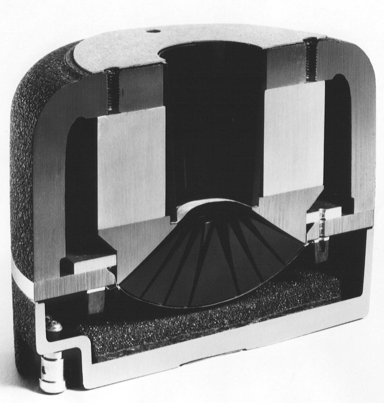
A compression driver mated to a waveguide is needed. Horns fail to adequately control directivity generally, and the exceptions have lesser sound quality. The waveguide should match the mid in dispersion at the crossover point. Typically this means a 15" waveguide mated to a 15" driver.

2. High efficiency

The speaker described above will have high efficiency. 97 db can easily be achieved. A conventional large hifi speaker will have 89 db at best. Even where large drivers are used, the efficiency is low due to the extension. In keeping with our goal, our speaker will have to either be very large, or accept less extension. Typically it will be better to trade off extension and use a 3 or 4 way system.


3. Low compression

Again as a bi-product of the controlled directivity and high efficiency, we will have also achieved low compression.

4. Absence of resonances

Here we need to choose good quality drivers. Breakup in the bandwidth should be avoided. Drivers generally have well controlled breakup with a smooth native response, or a very sharp peak at the top end. Both can be used effectively, but where the peak is very sharp, it should be sufficiently removed from the crossover point.

5. Distortion profile

This can be determined with measurements and generally indicates good driver design. Where these measurements don't exist, one can choose drivers that are known to be generally of high quality. Typical examples include Acoustic Elegance, B&C, PHL, 18sound, Precision Devices among others.

6. Wide bandwidth

In a 3 or 4 way system this is easy to achieve. Consider the extension that is necessary. For a music only system, consider a 3 way system. Essentially this can be a passive two way with one or a number of subwoofers. For a music only system, consider using more efficient drivers that are better described as woofers. Consider 15 or 18" pro woofers in a vented alignment.

For home cinema, efficiency must be traded to achieve deeper extension. It's certainly worth it. Start with one LFE sub that meets output and extension targets. It may be a few subs clustered together. Greater efficiency is gained in this way.

7. Minimised very early reflections

Controlled directivity helps in this area a great deal as well. Placement is also important. Toe in the speakers to avoid side wall reflections and where placement close to boundaries can't be avoided, use treatment to tame the ill effects.

8. Live vs dead acoustics

Controlled directivity speakers require less treatment, so the problem of a dead room is avoided. Consider diffusers on the ceiling and rear wall, although be careful with nearfield placement.

9. Smooth bass response & rapid decay time

Start with a room that has some damping. Plasterboard (drywall) lining is preferred, with two layers joined with a flexible adhesive such as Green Goo. The cavity should be insulated. Then add bass traps - as many as you can fit. A rectangular room has 20 corners. 4 of them are vertical, 8 are horizontal and the remaining are tri corner where both walls and ceiling or floor meet. Add broadband bass traps to as many of these as you can. This will smooth out mode issues and also reduce modal ringing.

Next, find the best placement of speakers and bass sources.

For a small room with a small seating area, one sub may be enough. For a bigger area where you want consistent bass in every seat, you will need multiple subwoofers. The first should meet output and extension targets, the others fill in dips which persist even after bass trapping.

Then after all else is done, you may apply some EQ to reduce peaks. It's important to ensure that the correction does not create problems in other parts of the room. EQ works more for a music system in just one small area and may not be useful at all in a large room with many seats. One may be improved at the expense of another.

None of this can be properly optimised without measurements.

10. Time alignment

Time alignment can be achieved by various methods. The best for DIY enthusiasts is with a digital active crossover.

11. Response shaping

In the system described so far, this is quite easy. Passively you can do it with an L pad on the tweeter. Actively you simply adjust the gain and in either case, the subwoofer will have it's own gain control. I don't recommend magic EQ boxes. If used, it's important to understand what they are doing. Sensible correction involves a room measurement for bass and a gated measurement for everything else. Even this can be done incorrectly. They may be an improvement for uninformed users, but there's a good chance that a capable DIYer can achieve a better result with a manual system that they can control and tweak over time.

12. User adjustment

The system described here will be easily adjusted with greater precision than tone controls and the result will be a satisfying balance.

Overall the synergy that is achieved here will count for far more than lesser important issues like choices of cables, DACs, preamps and sources. Of course, valve based systems do have different requirements and so that would tend to skew priorities and make matching more critical. Amplifiers also have more critical compatibility issues than most components. Some amplifiers are speakers are just not suited, in particular due to the impedance load. Class D amplifiers also have not yet reached the level where they are ideal for treble. However, once basic compatibility issues have been addressed, excellent performance can be achieved with low cost components.

What does all this mean? It isn't cheap to set up an accurate sound system. However, it's possible to put together such a system mostly with components that are low cost. Insert these low cost compatible electronics into a well set up and well rounded system that meets as described here and they will far exceed the performance of much more expensive "high end" systems that neglect these issues. You could choose all the drool worthy components - turntables costing more than a luxury car, snobby cables costing more than many complete systems, amplifiers built with unobtainium and speaker cables made from cantaffordium. Now put them in a room with no treatment and no consideration of speaker-room synergy. Now all that you have gained will be masked by big problems. The bass will have big swings of +/- 20 db and never mind the fast transient response of those little sealed woofers. It will be completely swamped by modal decay. Those woofers might stop fast, but the room won't.

Don't get me wrong, the high end system should still sound excellent. It will simply fail to yield all of it's potential. It can easily be beaten by a well rounded system with more attention paid where it counts the most. In many cases it would not be difficult to spend 20 - 50% and get a better result.

For those with high end systems

If you already have a system put together with high cost high end components, are you getting the performance you paid for? If you are like most, probably not. I have some suggestions for you. Firstly, focus on learning some new tricks. Learn how to measure the bass in your room. Use those measurements to assist in placement. Read up as much as you can. Secondly, invest seriously in room treatments. Get as many bass traps as you can. Thirdly, make your speakers and the room the most serious investments in your system. And if you have SAF issues with treatment, do whatever you have to do to get a treated room. You might have to be creative, you might have to get something custom made, you might have to resort to bribery and corruption. No excuses!

You might also consider a speaker which is probably very different to what you have now - Gedlee Summa or Abbey. For some of you high end guys, those two speakers are too cheap to be taken seriously. I consider this speaker to be state of the art.

What really matters in audio

There is a lot of talk on audio forums about the least important parts of the audio chain. It's very common to major on minor issues. The curious trend with many is to neglect the much more important aspects at the same time. If you are the kind of enthusiast who wants to get the big issues sorted, here are some suggestions.

The big picture

The audio chain looks like this:

Original performance > Studio recording > CD > DAC > preamp > power amp > speakers > playback room

Of course there will be variations, but by far the three most critical parts of the chain are:
  • Recording
  • Speakers
  • Room acoustics
All of the other parts have audible effects, but the difference between a low cost but decent component and a high end component is relatively small. This doesn't stop many from declaring their differences to be huge, however, under controlled blind test conditions those huge differences aren't supported by the results. At best, those with a discerning ear can pick the differences, but that hardly supports the claim that differences are huge. Instead, it confirms my position that they are subtle and best considered as the icing on the cake for those with a system that is state of the art in the areas that matter most.

You have no control over the recording, so that leaves the speakers and the room.

Synergy

Synergy is a popular word in audio but it's often used where it matters least. The most critical synergy exists between the speakers and the room. They should be considered together, rather than simply choosing speakers then patching up it's problems with treatment.

Conventional speakers pay little attention to their interaction with the room. There are three types of speakers that stand out as having a better thought out room interaction - omni, dipole and controlled directivity.

Omnis radiate evenly in all directions. This can be desirable for a background music system, in which their large sweet spot is useful. If you don't have a listening chair, and listen well off axis then this type of speaker can be well suited. For critical listening they may not be the best choice.

Dipoles reduce lateral reflections (ceiling and side wall and potentially floor as well) while adding extra ambient delayed reflections. In effect this is like having room treatment without making the room sound dead. You can aim the null towards the first reflection point and cancel out first reflections off the front and rear walls.

Controlled direcitivity speakers seem to have the most compelling room interaction. With a waveguide they are able to achieve a flat response over a wide area. This means the room reflections are less coloured. The higher directivity means less absorption is required and this is very desirable. In a small room there is a trade off between dealing with reflections and making the room dead. Too little treatment will leave the problems. Too much will make it sound dead.

The key factors

1. Controlled directivity

A speaker should aim for a relatively flat response across a 60 - 90 degree window, and this should be achieved over a wide bandwidth as much as possible.

2. High efficiency

A speaker should not be required to use it's full rated power to achieve output targets. Typical drivers have around 5 db of power compression at their full rated power. Efficiency is a key factor here and is also a big part of dynamics.


3. Low compression

A speaker should be designed to avoid dynamic compression of any kind. This can relate to the input power (power compression), mechanical effects as well as thermal dynamics and BL vs excursion issues.

4. Absence of resonances

Through extensive blind testing of speakers, Harman Audio determined that the absense of resonances was a key indicator of perceived quality. Issues such as cone breakup are key offenders.

5. Distortion profile

A speaker should have low overall distortion, especially with tall order harmonics. THD has proven ineffective at indicating perceived accuracy, however distortion is still important. Ideally we should aim for low distortion of all types, with increasing emphasis on the more obnoxious components.

6. Wide bandwidth

For a music only system, 40 - 20k is a worthwhile goal. Some may prefer to go a little lower depending on music preferences. For a home theatre system the extension should at least aim to reach down to 20 Hz, or perhaps as low as 15 Hz for bass nuts. I don't recommend extreme goals here, since a great price is paid for extra extension. For a music only system I would much prefer to achieve 40 Hz with high efficiency than push an inefficient subwoofer to pump out 25 Hz at high levels.

7. Minimised very early reflections

Early reflections cause many problems. The worst example is perhaps a speaker placed right in a corner. It is not only the bass that goes out of control - early reflections create many problems. The sound is highly coloured, with boomy/peaky bass and very poor imaging. Where speakers are placed near any boundary, acoustic treatment is necessary. Ideally it would be better to either avoid this completely, or flush mount.

Another form of very early reflection is baffle diffraction. Sound waves travel along the surface of the baffle until they reach the corner. They diffract at that point, causing a secondary delayed source.

8. Live vs dead acoustics

The room design and treatment should aim to avoid problems without the over-use of absorption. Ideally this would involve room design as well as careful treatment which includes absorbers and diffusion panels. Too little leaves the problem. Too much makes the room lifeless.

9. Smooth bass response & rapid decay time

Every room has modes in the bass range typically from 40 - 200 Hz. These cause the bass to ring out in the time domain. Modes create peaks and dips in the response and decay at a slower rate. This causes the bass to sound unnatural - boomy at one moment, missing the next.

It is possible to flatten the frequency response without fully correcting the problem. It is necessary to resolve the time domain as well. 

10. Time alignment

Time alignment is an essential part of maintaining accurate imaging. Crossover filters as well as misalignment of acoustic driver centres cause the sound to arrive at diferent times. This can be corrected and allowed for in the design.

11. Response shaping

A ruler flat response is the ultimate only in a perfect world.  In reality, some response shaping is a better goal. Overall a flat direct field response (from the speaker without any room impact) should be the starting point. The tweeter level should then be reduced slightly, typically to around 2db. Then with a farfield measurement, the bass level should run at about 6 - 10 db higher the the midrange. This combination will be perceived as accurate with decent and balanced, although the bass may be too much with movies where the bass level is already increased.

12. User adjustment

Recordings vary a great deal, with various tonal balances. Ideally it should be possible to adjust the bass and treble level quickly and easily, although tone controls will often be inadequate since they provide EQ that will often mess up the response.


Now, let's see how these goals can all be achieved >

What is a compression driver?

A compression driver (CD) is a professional loudspeaker driver usually intended for mid or high frequency use with waveguides or horns. They can be thought of as similar to hifi dome tweeters in that they have a dome diaphragm and a motor. The main physical difference is that the dome is coupled to an exit tube via a phase plug where the dome is large than the exit. Hence it has a compression ratio, defined as the ratio of the area of the dome to the exit. Shown below is a section through an Altec compression driver:


On the left you can see the inverted dome, which enters through the phase plug with 4 expanding conical tubes, which combine at the throat which is also a conical tube. A horn or waveguide would be attached to the throat. It might be as large as 18" at the mouth. The advantage is clear - a very small lightweight piston can extend to high frequencies and yet it's tiny movements are coupled to a much larger area at the mouth. So you have the best of both worlds - the extension of a small light piston and the power and efficiency of a very large transducer. At the same time, the waveguide allows control of the dispersion. With a dome tweeter, the dispersion is controlled by the small size of the piston.


Here is another example:


Compression drivers can be used for high frequencies, midrange and even bass.

CDs vs domes

A dome tweeter will typically have about 90 db sensitivity and wide dispersion. It's dispersion if fixed by it's piston area and can only be changed by adding a waveguide. In this case a phase plug is needed and it's generally not as effective as using a CD which is designed from the outset for horns or waveguides. The dome will typically handle crossover points down to about 2 kHz with about 100w power handing when inserted into a speaker.

A compression driver intended for high frequencies will have a 1" exit and similar extension just shy of 20 kHz. Sensitivity will be around 108 db and while the power handling may be similar on paper, it applies to a lower crossover point and once padded to match the sensitivity of even an efficient 15" driver, it will have a power handling of at least 1kw and far greater output. The directivity can be controlled and matched to the midrange driver and so it is much better suited to custom design.

THX reference levels

The goal for a THX system to match the commercial cinema is 105 db at the listening position. This is the level reached in a commercial cinema when sitting 2/3 into the auditorium.

Seating distance: 3m
Power amp: 100w


Attempt 1: dome tweeter

First, let's try to achieve this with a dome tweeter. We start with 90 db at 1m with 1w. In theory, 10w yields 100 db and 100w 110 db at this distance. At 3m the level will attenuate between 4.5 - 9 db. So the tweeter level will be between 100 - 105 db. Power compression will rob some of that output by as much as 5db at the full rated power, but we can expect less for short bursts. So in the worst case scenario we get 95 db which is half as loud as our target. In the best case scenario we only just make it to the target and it's likely that the tweeter will struggle. If the amp is clipping, then the tweeter may be at risk and the sound may indeed be quite harsh. The ear becomes more sensitive at this level, so any problems are heightened.

Verdict: 100 db is probably the useful limit. A little more is probably possible, but undesirable.


Attempt 2: compression driver

Now let's try it with the tweeter that is meant for this kind of output. The right tool is the one that can do the job with a decent amount of headroom. We'll start with 108 db @ 1m with 1w and 118  db with 10w. If we double that power twice, we get 40w input and 124 db. The amp will not clip at this point so we are in a safer region. We'll take the conservative distance compensation so we get 115 db @ 3m. We now have twice as much output as our target, so in reality we can dial the power back so that we reach our target with only 4w!

Applying the same rules as we did with the dome tweeter, we can get 118 - 123 db output at the listening position, but this is far more than we need. This level exceeds many rock concerts.

The point should now be clear - compression drivers are the right choice for reaching THX reference levels. However, if used well they have other advantages as well, including most notably the ability to control directivity.

Introducing B&C DE250

B&C DE250 is a great value 1" compression driver.

Update
I've now had a chance to measure this driver and now show a section along with some photos of the parts.

Photos, drawing and description >


I've just ordered a compression driver for my next series of speaker experiments. I have different ideas, but what they all have in common is this well regarded compression driver - B&C DE250.

So what is it? It's a compression driver, which is pro audio speak for a tweeter. In many ways it is like a dome tweeter, but it is designed to be used only with a horn or waveguide.

It has an inverted dome. The replacement diaphragm is shown above and this view is from the rear, with input terminals shown. Most of the unit is it's motor. This one has a 1.7" dome - being much bigger than a hifi dome it has greater power handling. It has a phase plug which directs it's output to a 1" exit tube. This is where the compression part comes in since the diaphragm has 2.8 times the area of the exit. That means it needs less excursion than a direct radiator, and that is before adding a waveguide. The dome has 2.8 times the area of a dome tweeter. To match the efficiency of this driver, a conventional dome tweeter would need to require 64 times the piston area of a 1" dome yet have the same low mass of the small dome and avoid any resonances or breakup that would plague such a large yet light piston. In short, it can't be done with existing methods and materials. 

What about ribbons? They do have a large driver area and high efficiency, but they generally have limited bottom end extension and the dispersion is problemmatic. Horizontally they have the wide dispersion  and vertically they have narrower dispersion but in both cases they vary with frequency. 

A compression driver can achieve constant directivity and this is where the other options can't compete. 

Curious about what is inside?

Looking inside

I have taken 

Now let's look at it's response.
The nice smooth response shown in black was measured at the mouth of an oblate spheroid waveguide (6"). In red you see it's response when used in a strange way - firing up with no waveguide so that it works as an omni source. The ripples are mostly room related and you will see this with any ungated measurement. The blue response shows a more typical measurement at 1m. A little EQ at 4k was used to get it flat and you can see an axial dip around 7 - 12k. This is most likely a dip caused by diffraction at the waveguide mouth, which would explain why it doesn't show up in the nearfield. 

Other compression drivers with a look inside:


December 17, 2010

Take the free bass trap test

Not convinced bass traps are really worth it? Let me guess - you think they are big and expensive, the interior design committee will never approve and they won't make that much difference anyway! They are toys for rich boys with golden ears.

You need to hear the difference they make. I'm not selling them (perhaps I should be).

The good news is you can try them free. You can rig some up in about 20 minutes, with parts you either already have, or parts you can easily get free.

What do I need?
  • foam of any kind in a large quantity - mattress, couch cushions, spare bags of insulation (hint: couch on the side of the road = free bass trap material). 
  • (optional) louvre door to reflect midrange but let the bass through - you don't want to absorb full range
  • timber
  • rope
Ideally, a basic measurement setup would also be good so that you can measure.

Where do they go?

For this test, corners only. Trap as many corners as you can. In theory a room has 20 corners. 4 of them are vertical where two walls join and run floor to ceiling. Those are the corners you want to start with. Two of them is a good number for the test, do more if you can. You should still notice a difference with just one, but if you do just one make it big, at least for this test. These traps aren't optimal so they make up for that with size.

Curious as to how there are 20 corners in a room? Count the tri-corner ones as well (2 walls + floor/ceiling) and you get an extra 8.

The traps straddle the corner on the diagonal. You don't have to fill it in entirely, simply put them across the diagonal and make them as thick as you can - ideally about one foot thick.

Basic instructions

If you have a louvre door, then simply lean it over the corner on the diagonal with cushions behind it. In that case you won't need anything else. If you don't have the door or a similar membrane, then you could use some long lengths of wood and simply tie the cushions onto the wood - otherwise they won't stay in place. The purpose of the membrane is to reflect midrange and treble so the room doesn't become dead. It has no bass trap function. Other traps use the membrane as an absorber, but this isn't one of those.


How will it sound?

If you use enough trapping, the bass will sound tighter and more controlled. It will sound more like the bass you get outdoors, except with greater output and extension. It is a clear improvement. It may sound like there is also less bass, quite likely due to improved time domain performance. In other words, the bass stops faster.

How will it measure?

You will see a flatter response, where the peaks and dips are damped. The worst room is a concrete bunker. The extreme opposite is an anechoic chamber that works down into bass frequencies. Bass traps take you progressively closer to the anechoic chamber, but in reality you probably can't have too much bass trapping.

The most significant change you will measure is the rate of decay shown in waterfall plots. Unlike EQ, bass traps will speed up the decay rate.

I tried this test myself:
Free bass trap test >

December 15, 2010

Room treatment primer

Here is a basic quick start guide on what you need to do and why.

Above: this is a typical room treatment setup using Real Traps products. Bass traps are used in the corners and portable absorbers are placed on side wall first reflection points.


In a room there are three regions that need to be considered:

1. Modal region (light red)

This region is dominated by room modes. You can see the peaks and dips although in many rooms this will be worse. Some EQ has been used to reduce a very large peak around 45 Hz and some care has been taken to tame this room. Typical rooms will often see +/- 20 db.

2. Geometric region

Above the transition point, called the Shroeder frequency, room modes become spaced together so closely that they smooth out. Thus we tend to overlook the fact that modes still exist and instead we pay attention to the fact that sound travels in a straight line and is reflected as geometry would tend to dictate.

 3. Pressure region

As wavelengths begin to become large compared to room dimensions, we no longer see peaks and dips but instead the room becomes uniformly pressurised. In this region, the bass response is smooth and if the room enclosure is adequately constructed, room gain will extend low frequency response. The lowest mode in the room measured above is around 45 Hz so the pressure region starts a little below that. This region needs no treatment.

It's interesting to note that in a car, due to the small cabin size the entire bass range is in the pressure region. This is why cars have so much bass even with small speakers.

Bass treatment


In the modal range, the goal is to add bass damping without adding any unwanted full range absorption. This will flatten out the frequency response and help the bass to "stop faster."

Have you ever been inside a completely empty room with no furniture, curtains or pictures? Because your ear can tell the difference between the sound of your voice and the room reverberation, you realise instantly that the room needs taming. In the bass range, the ear is not able to make that distinction, so the added reverberation is simply heard as bass that is lacking control and tightness. The subwoofer itself will often be blamed. Those who have not heard a properly treated room will also not realise the level of realism that can be achieved.

The answer is to use a bass trap, which is a purpose-built bass absorber. These are normally placed in room corners where they will have the most effect. For more information about bass traps, you may like to read:

Bass trap primer 

Midrange treatment

Absroption and diffusion are used to improve imaging and create the right level of reverberation. The amount and arrangement of treatment depends on the type of speakers used and a level of personal preference. Speaker such as open baffle and waveguide based designs which control directivity tend to favour less treatment, while more common speakers with wider dispersion tend to require more. It's important to achieve a balance. While you probably can't have too much bass absorbers (traps), you can certainly kill a room with too much full range absorption.

Diffusors

Diffusors break up specular reflections, and instead cause the reflection to radiate equally in all directions. The result is that sound waves travel a longer path before reaching  your ears. Ambience is retained, but the detrimental impact of early reflections is reduced. A room will tend to sound as if it were bigger and this is generally an advantage in domestic rooms.

A popular skyline diffusor

Diffusors should not be placed too close to your listening position - that would place you in their nearfield region. They require a certain distance to work correctly. If you listen in the nearfield, you will have certain artifacts that will interfere with imaging. As a general rule they should not be placed within 3m of the listening position by direct line of sight.

As with most things, use in moderation. Consider them on the front wall, ceiling and side walls near the speakers, although they should not cover the entire surface.


Absorbers

The first place these are used is on first reflection points, as shown in the first image at the top. This is the convention, although with speakers that control directivity more, this may not be necessary.


Early reflections are the ones that tend to confuse imaging. More delayed reflections are more readily picked up by the brain as being part of the room sound and so imaging is not affected.

Another less common use for absorbers is where non-ideal placement of speakers is required. Placing surround speakers on walls causes problems with the response, even if they are flush mounted. Treatment should be used. The same is true of main speakers which are placed close to a wall.

It's important to realise that the thickness of the material and it's distance from the wall impact the bandwidth. Very thin material placed on the wall will only affect high frequencies. To work down lower into the midrange, the panel needs to be thicker.

Next: room treatment suggestions

Room treatment suggestions

Do you want to just roll up your sleeves and start treating your room? Here are some suggestions with what to try. If you want to know the basic theory behind these suggestions, you might like to read:

Room treatment primer
Bass trap primer

Proof that acoustic treatment doesn't have to look ugly.

1. Main bass traps

Place two broadband bass traps in the corners behind the speakers.

Details: they should be around one door width on the diagonal across each corner, with rigid fibreglass which is more dense than regular insulation. Alternatively use foam or insulation compressed together. The thickness should be around 150mm, although you can fill in the entire corner if desired. Aim for floor to ceiling and trap all corners if possible.


2. Diffusors

Place a moderate amount of diffusors on the front wall behind the speakers, on the side walls and on the ceiling, taking care to ensure that they are no closer than around three metres from the listening position.

Details: consider skyline or QRD type diffusors.

3. Floor treatment

If you have a bare floor, a large rug is essential. Even in a carpeted room, consider doing this as well with the first floor reflection points.

Details: More thickness is required ideally than carpet for best results. It is a good idea to place some other form of treatment below the rug if possible.

4. First reflection points

Find the first reflection points then place absorption panels in these areas. This could mean up to 6 surfaces are covered.


5. Bonus bass traps

You probably can't have too much bass absorption, although you can certainly spend more money and time than you need to. After you have used porous corner broadband traps, you may want to also add some membrane traps.

Details: These are essentially sealed boxes placed on the surface of the wall/ceiling/floor. They have a thin membrane (3 - 6mm ply) and rigid fibreglass insulation which should not touch the membrane. Like all traps, they are best placed around corners, but they could also cover the entire wall or ceiling. They differ to porous traps in that they need to be on the surface, while porous traps benefit from being out from the wall.


Ethan winer describes them here >

Membrane traps are easily placed in a room as they take up less space. A room built with plasterboard/drywall tends to act like a large membrane bass trap, however, due to the uniform depth (and often lack of insulation in internal walls), the bandwidth is limited.

December 13, 2010

Confessions of a bass trap Luddite

For some time I believed bass traps were for those with a problem room and for perfectionists. As I considered myself a perfectionist who had a pretty good room for bass, bass traps were low on my list of priorities. Until it suddenly hit me that I already had the materials to throw some together. You can read about my weekend experiment that changed my views on bass traps here


Cutting to the chase, my mission in this article is to convince you that bass traps are essential. They will make such a big difference that you will wonder how you ever lived without them. In fact, unless you have bass traps, you haven't yet discovered how good your speakers or subs are for bass. 

There are plenty of excuses for not using bass traps, but I'm about to sweep them to the side and at the end you will have no excuses left.

Excuse #1
My room is very good for bass already

This was my main excuse. I considered my room to be one large bass trap. Plasterboard lining with a cavity (or drywall for those in the states) acts as a membrane bass trap and is quite effective. It's certainly better than concrete or masonry. My reasoning was that if the entire room acts as a bass trap, how much will adding 2% more achieve except waste time, money and space?

What is needed is broadband absorption and it's unlikely that any domestic room will have it unless designed professionally for ideal acoustics. Without bass traps, a typical room will lack broadband absorption so the result will be quite hit and miss. The only other exception would be a room that is unusually lossy. I have measured one room that would not need bass traps. It was a demo room in an audio retail store. It had a wall of glass on one side, another was open to the shop which was quite large and the ceiling had "acoustic tile" which is virtually transparent to bass. There was so little enclosure offered by the boundaries that bass trapping was a non issue. This would be extremely rare in a home environment. If you have such a room, you are very lucky indeed and you have my permission not to use bass traps. Otherwise, excuse #1 is out for you!

Excuse #2
I believe careful placement is enough

You are right that placement is important. Good idea to pay attention to both the speaker and listening positions. However, this won't do the whole job.

Placement is the first step, but it isn't the only step. It will affect how the speakers couple to the room, having an impact on room gain. Placement will affect how room modes are excited. Where you position the speakers will determine where peaks and dips are located due to room modes. Where you sit will determine which of those peaks and dips you will experience.

There is no way you can avoid those room modes having an impact. There is no placement that can do it. The modes will also create time domain problems, such as modal ringing. You can see this here:

This is quite smooth and better than most. A typical room will fit within a 30 - 40 db range, but in this case this room is +/- 10 db. I should admit that I did use a little parametric EQ at 45 Hz to tame a peak.
Placement is the first step, but it isn't the only step. It will never replace bass traps.

The modes are marked with red dots (not all included). Notice how the modes decay slower in time? One is marked in particular where it has only a very small peak that would hardly be noticed. Yet in the time domain, it takes much longer to decay. If the modes decayed at the same rate, then the response shape would not change over time. You can see that this is clearly not the case.

Excuse #3
I have a magic EQ box

Fix the frequency response and you will fix the time domain as well. This is the argument that is made, but it does not work. The response shown above does have some EQ and I have shown previously that the modes decay at a different rate. This can't be fixed by EQ alone.

I'm certainly an advocate of EQ as a useful tool, but it certainly doesn't do the same job as bass traps. If you are relying on EQ, you will often need to use some boost and this will quickly kill the headroom. The amount of power and excursion required is not practical. You would need to double up on subwoofers just to allow for 6db of boost, or double up again for 12db.

Bass traps and EQ are best used together. You can EQ a room with bass traps and it will probably be an improvement. If you bass trap a room that already has EQ you will see a bigger improvement. in many cases, a much bigger improvement and it will be global.

Don't make the mistake of thinking EQ can eliminate the need for bass traps. If you use both, you will see the difference in measurements and hear it clearly in listening tests.

Excuse #4
Bass traps are expensive

If buying bass traps presents a problem, consider building your own. It's not difficult and it's not expensive. If funds are really tight, then next time you see a dodgy couch on the side of the road, think "free bass traps." The cushions will work just fine. Add a little inventiveness and I'm sure you can put make something that will work just fine.

Excuse #5
I don't have a dedicated room

I've left the most difficult one 'til last. With a little creativity, you can come up with something that can get past the interior design committee. Consider ways that you can get them to blend in. Membrane traps are the easiest to integrate in this way, but it's possible to do the same with typical broadband traps. Imagine that your room had duct work built into the corners. Would your partner insist that those heating or AC ducts have to go or else? Would your partner insist that the fireplace chimney has to go because it's just too big? What about that huge freezer?

These things are accepted because the function is understood and given a priority. You can't have a fireplace without the chimney. Just like you can't get high end bass without bass traps. I don't expect every partner will accept that idea, but if you can tackle the challenge creatively and make it work visually, you have a better chance. And if all else fails, bribery in the form of jewlery can be a wise investment.


"Ok, you've convinced me..."

You can find quite a few bass trap plans online, but first you need to understand how they work and how the various types are different. My bass trap primer will save you reading through many different pages on the internet that will still leave you wondering about the basics.

Bass trap primer >

Bass trap primer

Here I'll introduce the basics of bass traps and give you enough information to start building your own. The topic is not complex, but for some reason a lot of the information online about bass traps is not very helpful.

Two modes of operation

Bass traps can work in two ways:

1. Pressure mode
2. Velocity mode

You don't need to fully understand what this means, but the implications are critical. Pressure mode traps need to be located very close to the boundary surface of the floor, ceiling or wall in question. The further they are from the surface, the less effective they will be.

Velocity mode traps need to be located as far as possible from the surface. They work best at 1/4 of one wavelength of the frequency in question. So to work at 100 Hz, ideally such an absorber would be 860mm in depth. In reality this ideal is not practical, but it should be understood for now that distance from the wall matters more than the thickness of the absorbing material.

3 types of bass trap

There are three types of bass trap:

1. Broadband
2. Membrane
3. Helmholz

1. Broadband traps

Broadband traps are recommended as the first to place in a room. They are porous velocity mode absorbers, so they should be placed as far away from boundaries as possible. They should be placed in corners since this is where they will be most efficient and typically they will straddle a corner and run from floor to ceiling. A typical design will be 600 - 900 mm across on the diagonal. The angle helps as the depth varies and tends to assist in working over a wide range.

As a minimum, aim for the two corners behind the speakers, but four corners is ideal. Next you may consider the corner between the wall and ceiling junction as well as the floor/wall junction.

Foam or fibreglass insluation can be used, but they are less dense than the ideal so should be compressed. The ideal material is rigid fibreglass insulation which has already been compressed so that it is more dense. You may choose to apply a face over the insulation to reflect midrange if you don't want the absorption, but ensure that it isn't too solid, which would may undermine the effectiveness.

Porous broadband traps are recommended because they can potentially work over the entire audible range. Other types have a much narrower range.

2. Membrane traps

Membrane traps are desirable because they can be very low profile, typically 75 - 100mm. They are pressure source absorbers so they must sit on the surface. This means they are the easiest to integrate into a room and you can paint them the same colour as the wall/ceiling.

The downside is they are resonant traps with a limited bandwidth. This means you will need to use a number of them with different depths to work over a broader range. Like all traps, they work best in corners, but instead of running them across the diagonal, they are best forming an L shape. So when putting them into a room, start with the corners. A rectangular room has 12 corners.

Essentially a membrane trap is a sealed box where the outside membrane would be 3 or 6 mm plywood or similar. Rigid fibreglass should be placed inside but should not touch the membrane. You can make it with 5 sides if you attach it permanently to the room and seal up the joins. If mobile, they require 6 sides.

They work as the bass exerts pressure to bend the membrane. Energy is absorbed in this way.

Membrane traps should be added after broadband traps have first been used.


3. Helmholz resonator traps

While these have an appeal as rare devices, they present a design challenge and are a more difficult way to achieve a result. The British Broadcasting Commission did some research on such traps and found them to be impractical due to their expense and various difficulties. They are senstive to misalignment and tend to need custom design for a particular room. They could be an interesting solution for someone with great patience who is willing to build many versions before getting it right. There are few who would persist and be willing to build many large traps before getting one them all to work well.

How should I trap my room?

1. Start with as many broadband corner traps as you can fit and make them as big as you can live with. Run them floor to ceiling if possible and aim for 4 in a rectangular room, or more if you have a different shape.

2. Next apply similar traps to other corners formed between walls/ceiling and floor/ceiling.

3. Add membrane traps next with different depths. Start close to the corners. If cost is no object and you have the space, then cover all surfaces you can with membrane traps. You probably can't have too much.

Naturally there is a balance to be found where you weigh up space, cost, performance and aesthetics, but I would consider two decent bass traps to be a minimum. If you simply stick a 400mm wide piece of foam in a corner, don't expect to discover what I've beent talking about.

December 10, 2010

Free bass trap test

A quick test of free bass traps. It suddenly hit me - I have the parts to try a couple of thrown together bass trap. Free bass traps!


As you can see, I've used louvre doors and a ladder with cushions from old couches as foam. Quick to rig up and no cost at all to try. The response doesn't fully reveal the result:

Green - before   Red - with traps


Two main peaks are removed, but surprisingly dips are made worse above 100 Hz. The waterfall plots tell more:

 
Before

While the response is fairly smooth, you can see evidence of modal ringing.

Bass traps added


Notice in particular how the decay rate is faster. Not only is modal ringing reduced, but the bass stops faster.
 

Overlay of both plots
 In the overlay above you can see how the before plot extends out further in the time domain. Please note: someone pointed out that I didn't have matching time scales, so it makes the bass traps look better. Here is the corrected version:


How does it sound?

The bass is tighter and leaner and cleaner. It is the kind of bass you don't normally hear indoors. It sounds like outdoor bass. Tight and punchy. More dynamic. It's a definite improvement and not a subtle one. The difference is like you might experience in upgrading from a $500 subwoofer to $3000.

This change has got me pulling out a lot of CDs I haven't heard for some time. Tracks that I could never get to sound right in the bass have fallen into place. Unlike EQ which tames a small area, the improvement is global. Reducing peaks in the response with EQ is a definite improvement, but at times it looks better on paper than the actual audible improvement. However, bass trapping improves in the time domain as well and the result is more audible than the charts might suggest.

December 9, 2010

TL speaker gallery

My TL article is the most popular in this blog. Many people around the world have built their own version and occasionally I hear from them with questions or feedback.

Have you built the TL?

If so, please share your experience. You might like to post your comments here. You might also like to share links to your photos.

Gallery

Mellow Fellow:
MF has a thread going on at Overclockers:

Build thread >

You can see he's come up with his own twist and there is some obvious skill there at coming up with a nice finish.


Steve B:
View the other photos >


Russ S:
View larger version


December 7, 2010

The biggest problem with blind testing

Nearly all blind tests have a major problem and here I propose a solution. It makes these tests far more revealing.

What is wrong with blind tests?

Some would say "what isn't wrong with blind tests?" Here I will focus on just one aspect. I'm in favour of blind tests, although they aren't my idea of a good time.

Most blind tests suffer the same problem that plagues sighted tests. They both usually rely heavily on audio memory. As a result, in order to compare one has to process the test sample, form some kind of opinion, remember what was heard, then compare it to the next sample. This can work fine for major differences, but normally blind testing is used to try to make valid comparisons involving subtle differences.

No matter how scientifically conducted, any blind test that relies on audio memory is seriously limited. 

Trusting your eyes vs ears

Our visual acuity is generally better than our auditory perception.We pick up more information from what we see, with greater accuracy and we also generally remember what we've seen with greater accuracy than what we've heard. If presented with contradictory visual and auditory information, which one do we believe? If we see the source of a sound coming from location A but it sounds like it's coming from B, what is our conclusion? We will trust what our eyes tell us every time. Our instinct tells us that our eyes are more difficult to trick than our ears.


 In the image above, the left side of the gray donut appears darker than the right. However, in the image below, the only change is that the red line is removed. Now you can clearly see that this is a trick - there is no difference in tone between the two sides of the donut.


In order to pick subtle differences in tone, our eyes need to see the two side by side with nothing in between. A single line between is enough to allow the background to throw us off. This is a simple example, but an audio comparison includes many tricks which are not so easy to demonstrate and identify.

A blind test represents a much greater challenge, so greater care should be taken to control any factors that might skew the result.

Instant switching

Fortunately it's quite simple. If you are comparing fairly subtle differences, you need an instant switching mechanism. When this is done, audio memory is note required and tiny differences are instantly revealed. If there is a change in tonal balance, it will be noticed immediately on the switch. If the sound stage is affected, instruments will suddenly move. Any difference that can be heard will be revealed with much greater clarity. False differences are also eliminated. Previously you might think you heard a difference that was simply an auditory illusion.

Gainphiles instant level matched switch box
Shown above is a switch box that Gainphile made up for a recent listening test of active crossover units. It switches both inputs and outputs of 4 channels, where one of the inputs can be attenuated to match the other. A box like this could be used to test interconnects, DACs, active crossovers and preamps.

More about blind tests

If you are interested in blind tests, you might also like to see some examples a blind test results that have been posted online.

Blind test results >


Why is blind testing such a hot topic? >

The best threads ever created

Serious DIYer? You must read these threads ...

Geddes on Waveguides

Multi subs

Do cables really make a difference? 

Amplifier testing
Many high powered amplifiers tested, typically pro amps that suit DIY subs.

Subwoofer testing
A large range of subs tested, commercial and DIY all under the same conditions.

Ok so my list needs some work ... feel free to share threads you think are some of the best.

December 5, 2010

Behinger Ultradrive DCX vs MiniDSP

MiniDSP vs DCX - most DIYers looking for a good low cost active option will be choosing between these units. Which is the better choice?

In general I would tend to recommend MiniDSP as the first low cost option to try. 


It performed slightly better in listening tests than DCX and it's filtering options would tend to give it a further advantage. The digital converters can be easily bypassed where external DACs are used, along with digital input. While DCX supports digital input, it is setup for AES which won't suit consumer equipment. While it can accept SPDIF, the level needs attenuating which negates the advantages of having a digital input.


DCX can be improved with supported modifications, but the cost is considerably more than the unit itself.


Active crossover listening tests - conclusion

The process of evaluating active crossover units has been revealing. My findings briefly are:

1. Instant switching is critical for evaluating subtle differences.

2. Digital active crossovers may not be compatible with tube preamps. Some attention is needed regarding gain structuring.

3. The units were comparable regardless of price - the differences could be picked by some and not others. This would suggest they are quite subtle. (Note - we did not adequately test DEQX so it is excluded from that comment).

4. All the units were transparent enough to satisfy the majority of DIY speaker enthusiasts.

Tube systems

If you have tube preamps and power amps, then you may have trouble with any of these DSP units. You could use MiniDSP as a development tool and then have an analogue crossover made up. Or you might find a solid state preamp gives better results. 


Sonics vs features


In a test like this, attempts are made to level the playing field. In an actual system, they will all sound different as they have different filtering options. DEQX allows steep filters up to 300db/octave as well as advanced time and phase alignment options. DCX only allows textbook filters while MiniDSP allows advanced custom biquad filters. The modded DCX has a remote control. DCX has an auto align feature for time alignment, while with MiniDSP this can be done manually. 


In general I would tend to recommend MiniDSP as the first low cost option to try. 

More about DCX vs MiniDSP >