Previously I referred to this compact bandpass sub, originally proposed for a client requesting a bandpass sub. However, I quickly realised it was ideal for another client seeking a quality compact sub for a lounge room system. This sub would be hidden behind a couch - I had already tested all viable positions in this room and determined that this particular location was ideal.
A classic driver
This sub is built around a variant of the classic Peerless XLS series of sub drivers.
Given the vast array of drivers now available, the classic drivers are often overlooked. However, this project serves as a reminder of that clean and articulate bass that made this series of drivers legendary. The particular variant I'm using here is the Scan Speak version - 30W/4558T00.
As with all Scan Speak drivers, we see excellent build quality, including a die cast aluminium frame which is well ventilated along with an aluminium shorting ring to lower inductance. Unlike more typical modern drivers, the surround is quite large relative to the linear excursion capabilities of the driver. Hence at xmax, this driver is not in any way pushing the limits of the suspension system. The modest 51mm diameter voice coil along with the shorting ring means a very low inductance value of 0.83 mH.
4th vs 6th order bandpass
A 4th order bandpass, such as we are using here, offers a few advantages. Firstly, the sealed rear chamber provides inbuilt excursion protection. Even if we aren't using a rumble filter, the driver is protected from extreme excursions by the sealed air spring in the enclosure. 6th order and ported designs don't offer this protection and this means they require a high pass (rumble) filter that is not adequate on many plate amps and which is not available on AV receivers. This usually means we need to add an external DSP device. In this case, a 4th order design meant we could simply use the DSP filters built into the AVR. The enclosure is also smaller than a 6th order design.
How does it sound?
Exactly as expected with this driver, the bass is clean and articulate. True to its name, the bass is punchy due to its tuning. As this is a fairly casual system, mainly used for music and Netflix, this client wasn't aiming for the kind of LFE extension home theatre enthusists normally choose. From the very first test sweep it was clear that this would be a trouble free sub.
Shown here is the nearfield response. You can see the port resonance at 520 Hz. The chamber is lined with 50mm thick high density acoustic material, which is very effective at damping port resonances. This is no the lining that you normally see in speakers and subs. It's extra high density Martini Absorb XHD, as used in bass traps. The lining typically used in speaker boxes is often not adequate for a bandpass design.
Cabinet design
The driver is surface mounted onto a double thickness internal baffle (36mm thick) and secured with T nuts and cap screws. The driver faces a sealed chamber adjacent to the 200W plate amp. This provides excursion protection. The driver magnet faces the front chamber, which has a rectangular port. The internal baffle is heavily braced on both sides and the result is a very inert cabinet.

In this design I've opted for a rectangular port. It performs better than a shelf port due to reducing the surface area. A shelf port extending all the way to the sides would have higher port compression. A round port limits the options for getting the right length. In this design, I needed precise control over the port area, so that I could get it to terminate at the internal baffle. With a round port, I'd have to accept big steps in sizes. With this design, it took some careful juggling to get both volumes optimised and to have the port match the depth of the rear sealed chamber. Round ports also introduce some challenges with flaring the inside and also with build sequence.
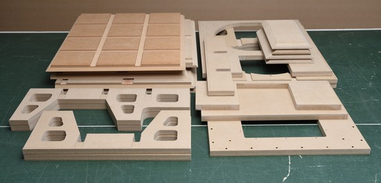
Flat pack
As with all our builds, a CNC machined flat pack is available.


 Lowering the internal baffles into place.


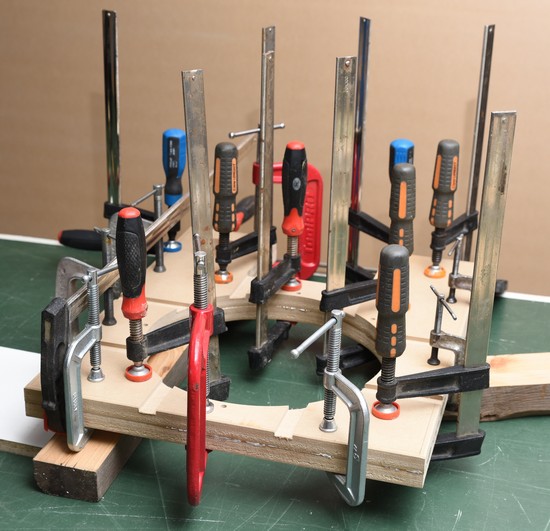
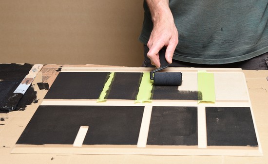
 Solid timber braces put into place. These will be glued in place later. The absorber panels are already glued in place. Later, access is impossible. The unpainted parts are the trenches on the sides, top and bottom.

 I haven't taken photos of the assembly of the solid timber braces and the port, which has four pieces, with round overs on both inlet and outlet. There is also a brace not shown. This part of the build was fairly involved, with many panels being secured in rapid succession. It's difficult to handle the camera when dealing with polyurethane glue.


