
November 27, 2011


November 19, 2011
The Illuminators
I had a chance to listen to some SGR Illuminators this afternoon.


These were featured at the Australian Hifi show in Melbourne a few weeks ago. It's an active speaker and what surprised me was how hard this thing can hit! The accuracy was no surprise - I expected as much.
These were featured at the Australian Hifi show in Melbourne a few weeks ago. It's an active speaker and what surprised me was how hard this thing can hit! The accuracy was no surprise - I expected as much.
November 14, 2011


November 12, 2011
Room measurement case study 1
Here is a case study of one room that I measured as a preliminary investigation. The purpose of this measurement session was to determine how well the proposed plan will work in the region dominated by the room, below 200 Hz. This is Graham's home theatre room that will soon have some Ewaves and some 18" bass bins for some Peavey 18" pro woofers. We measured 10 potential bass box locations and four listening positions to represent two rows of seating. Since this is a preliminary investigation and the final speakers have been built, an Osborn floorstander was substituted. Once all speakers and bass boxes are complete, measurements taken for bass integration are different.

Positions 2 and 4 were desired so bass bins could be built under the screen, after some work on the front wall.

Here you can see the measurement setup - I brought my PC equipped with software to measure the drivers and the room, as well as simulate a suitable bass bin design. Positions 7, 8 and 9 are across the rear wall and 10 on the side wall. Ignore the location of the mic stand!
The mic and bass speaker positions were reversed, so the speaker went in the listening position, then the mic was moved. This works fine for a preliminary assessment, and speeds up the process.
First we establish that the baseline, testing the speaker used for bass with a nearfield. The speaker in question is a conventional ported floorstander, chosen because it's bass driver is near ear level and also due to the ease of measuring into the lower midrange.

Nearfield measurement of port and driver:

The smoothness of the response is due to the absence of room influence. The mic is placed very close so the measurement is dominated by the direct field. In looking at all following charts, keep in mind that this speaker is not flat all the way down and has roll-off below 30 Hz.
Front corners and centre front:

All three show a strong 50 Hz mode, but the centre position is smoother overall than the corners. You can see how the corners together could smooth each other out. Out of these three, the best single sub solution is the centre. As it turns out, Graham had already chosen this position for a Shiva sub.
Centre (grey), and positions 2 and 4 under the screen.

Both these positions combined work out similar to the central position.
Waterfall plots show decay behaviour.
Here we are looking for modal ringing.
Corners vs centre position:

If this waterfall doesn't display as animated, you may need to right click on the image and open in a new tab or window.
From the main listening position, right corner:
 Left corner:
  Centre:
Among other things we learn that this room does not support low bass well. It isn't surprising since it is a large lossy room, with a lot of openings, windows and light construction - timber floor, plasterboard (drywall) light framed walls and ceiling. Notice how the centre position excites the dominant 50 Hz peak less strongly and up to about 120 Hz the decay is more even with less ringing. Above about 150 Hz, all three positions have a lot of ringing in a region where it is sonically a bigger problem for psychoacoustic reasons. This suggests that a suitable treatment scheme might include distributed small bass traps that are effective above 120 Hz.
All measurements from the main listening position:

Confusing? Absolutely, but also useful. Two things stand out - the dominant 50 Hz mode and the roll-off below that point. This suggests that EQ will likely be effective to tame that peak and that brute force is needed to get extension in this room.
How good is the bass where the mains are positioned?

Front centre (grey) is compared to the left and right main speakers in their current position. Note: we didn't measure the actual current main speakers (Bose 901), but instead the response using the same Osborn speakers. With both positions together, the result is fairly similar, although on an individual basis, the centre position is smoother. The lower midrange is likely to lack body and fullness in the lower midrange, based on this measurement.
Four listening positions were measured, but for the sake of brevity, I won't show them all.
All measurements from the rear row (middle position):

Compared to the previous position some trends can be seen. The 50 Hz mode is still present but we also see more extension and a 30 Hz mode related to the room depth along the listening axis. When we move back closer to the rear wall, the room is now able to support the axial depth mode. We also notice some dips around 50 - 80 Hz which will unfortunately cause a loss of bass impact, and here we start to grasp a problem with optimising multiple rows in a big room. If we achieve extension and bass impact in the main position, the back row will become bass heavy, with a bloated bottom end and missing midbass. A simple solution such as one sub with some EQ will not optimise the entire room well. One choice might be to focus on the prime position and let the chips fall where they may elsewhere. Or a more sophisticated bass integration may be chosen to get more consistent results.
Front corners vs centre:

Now you can see the extra extension and midbass suckout.
Corners vs the centre (back row):
 If this does not appear animated, then right click and view in a new tab or window.
Left corner:

Centre:

Right corner

So what happens if we add another sub in a different position?

Front centre shown in grey, compared to the rear corners (green right magenta left).
Now we can see that the midbass suckout is removed. A small sealed helper sub could work well here with some care given to avoiding localisation. A bandpass sub with a sealed rear chamber and a 75 Hz low pass with a steep slope would be a good place to start.
How would this affect the main position?

This helper sub if made sufficient in extension could add some bottom end by as much as 10 dB at 30 Hz and the right corner could smooth out the midbass as well. A little more EQ is needed around 50 Hz. Overall, it appears that it would actually improve the main position as well.
This is a preliminary investigation. The final speakers will need to be measured in place with the chosen bass management settings, treatment and EQ all in place in order to fully optimise the bass. So at this point, we are looking at the big picture and aiming to find the solutions most likely to work.
Bass bins
Graham bought my Peavey 18" woofers to go in some bass bins under his screen (positions 2 and 4). We ran some sims using these drivers in both a vented and tapped horn design. As much as I was hoping he might go for a tapped horn for the fun of it, I had to admit I could not see any major advantage in the sims. We came up with a large vented box with a slot port.
How do these positions measure in the four measured positions?

Superimposing all positions, and both bass bins, again noting that they aren't built yet, but we are looking at the measurement with substitute speakers, we can see the greater extension in the rear row.
Main listening position:

Clearly they are smoother together.
Left seat in the front row:

Rear row placed 1.4m from the rear wall:

Both share a deep notch at 60 Hz.
Rear row moved closer to the rear wall (750mm).

All up around 50 sweeps were taken and much of this data isn't shown here.
3 sub options
Now many are familiar with a certain Harman paper on multiple subs. It recommends subs at the centre of the front and rear wall for many rooms. This turns out quite well with peaks and dips often coinciding:


Conclusion
Now many are familiar with a certain Harman paper on multiple subs. It recommends subs at the centre of the front and rear wall for many rooms. This turns out quite well with peaks and dips often coinciding:
Unfortunately due to a window this is purly academic. If the rear right sub is added, the suckout is also removed:
Conclusion
From these results we can see:
- the proposed locations will work quite well
- two bass bins are better than one in terms of smoothness
- the current sub position (front centre) appears to work best as a single sub solution
- the front row is reasonably smooth but lacks extension
- the rear row has midbass suckout but greater extension
- a rear corner helper sub has the potential to solve both problems
- bass trap treatment should ideally focus on absorption down to 50 Hz along with distributed smaller traps to target the region above 120 Hz
- a good result is possible in the front row with one sub, moderate EQ and compact bass traps
November 8, 2011
Point source horn measurements
Point source horn measurements taken on my polar measurement rig with Arta. Shown below are directivity plots.
See measurement setup >
1. Yorkville Unity
2. S1 - my first prototype (60 x 60)
3. S2 - my second prototype (90 x 45)


What do they show? The Yorkville has a pattern that narrows around 2 - 3k, revealing that the compression driver when mounted on the horn is starting to beam at the low end but when it transitions to the mids, probably somewhere around 1 - 1.5k, the pattern becomes wider. The horn is too small to control directivity any more, a compromise to achieve reasonable size.
S2 is a larger horn which manages to control dispersion more, however it does have some dips on axis, hence it requies some toe-in so that it isn't heard directly on axis. As a result, the plot could not be normalised like the others. A normalised plot is based on a perfectly flat on axis response.
S3 is much larger again and controls dispersion all the way down to 300 Hz, a very good result. The dispersion is more uniform than the others, most likely due to a combination of size as well as a second flare angle to avoid beaming. With S1 there is some slight beaming at the bottom end of the compression driver's passband, below about 1.6k. With S2 the transision is perfectly smooth, and there is nothing in the polar response to suggest the crossover point, while in the other two you can see changes across the crossover.
These plots show the same data, but now it is shown in 3D rather than a birdseye view with SPL represented in colour. Again the order is the same:
1. Yorkville Unity
2. S1 - my first prototype (60 x 60)
3. S2 - my second prototype (90 x 45)


At a glance you can see that the third (S2) is overall much smoother than the others. Both the Yorkville and S1 have some dips on axis suggesting that toe-in should be used to get the smoothest response. This isn't necessary with S2.
Overall this represents very good results.
Now some comparisons:
The dark line shows the - 6 dB point which is the reference for a given nominal dispersion. The straight line shows the nominal intended dispersion.


November 7, 2011
The Dunning-Kruger effect
The Dunning-Kruger effect provides some very interesting insights into human behaviour, with implications for the audio community. What is it? In a nutshell, it refers to the tendency of the unskilled to be overconfident because they simply don't know what they don't know.
Kruger Dunning effect in more detail >
There are two sides to it. There are those who over-estimate their abilities due to ignorance - this is referred to as illusory superiority, a form of cognitive bias. Others tend to under-estimate their abilities, partially due to being more informed and aware of their own limits, and perhaps overlooking that most others are not equally competent.
Do you suffer from illusory inferiority? If so, people probably praise your abilities and you feel that you don't quite deserve the acclaim. You might feel the need to balance it out by pointing out how much you still have to learn. If that's you, give yourself a pat on the back! You probably don't give yourself the credit you deserve.
Do you suffer from illusory superiority? If so, you probably aren't the one that is suffering. It's others, who see things that you can't, or don't want to see. Jesus had wise words to say that relate to this issue. "As a guest, don't take the highest seat so that the host has to ask you to step down and give it to someone else. Instead, take the lowest seat so that the host can then offer you a better one."
What to do about it?
Two suggestions:
1. Encourage those who under-estimate themselves, give them the kudos they deserve, despite what they say they will appreciate it.
2. Ignore those who blow their own horn. Smile knowingly. Life will dish out what is deserved.
November 5, 2011
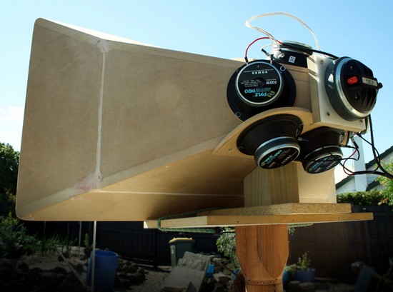
Point source horn directivity measurements

After the construction of my polar measurement rig was complete, I had a couple of friends (Andi & Roger) over to help with some measurements. Andi brought his laptop and Arta, Roger brought his Yorkville Unity horns, shown below:

Roger is standing there to make sure it stays on the stand! It is very high up in the air.

We also measured the 8" B&C woofer in my prototype surround speaker.
S2 from behind.

Subscribe to:
Posts (Atom)