Jump to the next Waveguide Shootout >
In one day we compared a bunch of compression drivers and waveguides. We first started measuring outdoors. You can see Andi's canon ... oops I mean diy mic pointing at the flashy 12" waveguide. Our measuring was followed by some listening comparisons with a few torture tests indoors. The results were quite interesting. Did the ones that measure the best sound better? Did we all agree?
All four attendees were
StereoNET members - Gainphile the host (Andi), Antripodean, Fury and myself.You can read about the even on
StereoNET >
Measurement Setup
The speakers were elevated on a rotating turntable with 11 degree increments marked. The mic was also elevated and a Laptop setup with Arta, which proved quite powerful and revealing.
Our aim was to investigate various driver and waveguide combinations, see how they measured and how they sound. The crossovers were all done by Andi with MiniDSP and a level of phase correction was applied on the spot.
Understanding the plots
The directivity plots shown will be unfamiliar to many, but they are not difficult to understand. They are essentially a frequency response plot which measures from on axis right out to 90 degrees. This plot features an open baffle mid and a dome tweeter.
As you move across the x axis, you see how the directivity changes. The X axis shows frequency as with any frequency response plot, but the y axis shows the angle.
Region A (200 - 1kHz) shows where the mid has constant directivity due to the influence of the open baffle. This is very good performance and can't be achieved in any other practical design in this bandwidth. In this area it has 100 degrees dispersion, which means the response is 6 db down compared to the axial response. Region B shows a problem - the directivity is no longer contstant but narrows until it reaches 1.6k, then expands again. In region C it has constant directivity over a small range, but this time the dispersion is quite wide at 150 degrees. In D it becomes narrower again and in the top octave (E) it narrows from 60 to 40 degrees.
Plots such as these show problems in the crossover and problems with drivers integrating. A directivity plot of a perfect speaker would have constant directivity into the low midrange region. Across this region the directivity should not narrow at any point or reveal crossover points.
S15 Econowave
Compression driver: Selenium D220Ti (Titanium)
Waveguide: JBL clone
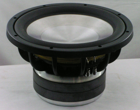
Woofer: Eminence Beta 12
The plot displays very good performance where directivity is controlled well over a wide bandwidth, with a little narrowing at very high frequencies. The achilles heel of this speaker appears to be the compression driver, which becomes quite harsh on dynamic material. I won't comment too much on the woofer because it was used in all of them.
18 Sound XT1086 + Faital Pro compression driver
Compression driver: Faital pro
Waveguide: 18 Sound XT1086
Woofer: Eminence Beta 12
This waveguide was quite different. It appeared to have a diffraction slot at the throat, then it transitions to an elliptical mouth. The driver has a novel orange phase plug.
The measurement shows that it's performance has a few glitches and isn't working quite as well as we might hope. At 3k it becomes quite narrow and very narrow at very high frequencies. However, in our listening session it sounded audibly better than the S15. It had a smoother sound and we suspected the drivers were the issue here.
Miniwave 3 way - OSWG6 + B&C DE250 + Vifa C17
Compression driver: B&C DE250
Waveguide: DIY oblate spheroid 6"
Midrange: Vifa C17 (see below)
Woofer: Eminence Beta 12
Vifa C17 modified
It was a surprise to the group that it could work well down to 2k, but this was what I had expected. The performance is generally quite good for a small waveguide, but there is a problem around 10k. It should be noted that the plots shown have been normalised. In other words, they show what the response would look like if the axial response was ruler flat. Here is the plot that has not been normalised:
This plot shows the response as quite good, with two issues. The first is a narrowing around 4.7k. It was necessary to use some EQ around here to get it flat on axis. The other issue is an axial hole around 9k caused by diffraction at the edge of the waveguide. This is an issue with most axi symmetric waveguides.
The solution is to toe them in to avoid the axial hole. Then only the narrow dispersion around 4.7k remains.
In the subjective comparisons this setup was preferred by all, although by this stage Antripodean was not able to stay. The sound was smoother and had less bite.
OSWG12 + BMS
Compression driver: BMS
Waveguide: Fibreglass oblate spheroid 12"
While we did listen briefly in mono, it was difficult to form an opinion.
Normalised plot:
You can see in both plots that it doesn't maintain constant directivity, but around 1.3 - 4.5k it becomes narrow.
Dayton 10" + Selenium CD
This combination has the best measured performance:
While it does narrow a little towards the top, the transitions are all smooth. Overall very impressive, but we didn't subjectively evaluate.
In our next event, we started using different drivers on the same waveguide, and one result in particular measured even better than these.


